Top performance with concrete elements

29.07.2019

Wind power towers are the supporting pillars of every wind turbine. They are subjected to great forces during wind power generation and absorb the resulting vibrations via the foundation - a challenge for statics, materials and engineers. At the same time, the annual electricity yield increases by 0.5 to 1 percent with every meter that a wind turbine gains in height. In this respect, the principle often applies at inland locations: the higher the wind turbine, the better the wind shear and thus the yield.

Top performance with concrete elements


Concrete-steel combination ideal for large heights

The hybrid towers of Max Bögl Wind AG are ideally suited for wind harvests from a hub height of 140 m and above. The lower part of the towers consists of concrete elements with a steel tube tip at the top. Tubular steel towers of this size are no longer economical because the material and maintenance costs are very high at these heights. Max Bögl Wind AG relies on the concrete strength classes C80/95 to C100/115 for the hybrid towers of the second generation.


Concrete from our own house

Max Bögl Wind AG relies on limestone and blastfurnace slag flour from its own production for the formulation of the self-compacting concrete (SCC) used. Thanks to this mixture, it is already possible today to save up to 50 percent of the cement content compared to earlier recipes. An in-house research and development department is working on further increasing the savings potential in the future. In addition to cost savings, the incentive behind this is CO2 reduction in cement production - and thus an even more active contribution to climate protection.


Photo: Max Bögl Group


Optimized in all areas

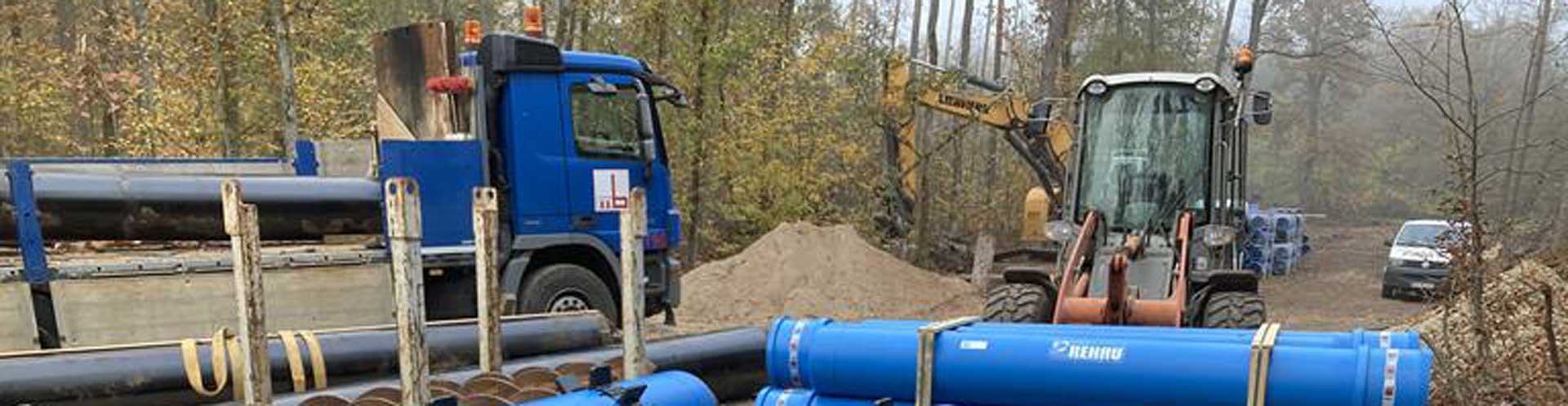
In addition to the actual tower concept, the engineers at Max Bögl Wind AG have also optimized the tower foundation, assembly, logistics and interior fittings of the hybrid towers 2.0. The new foundation design simplifies prestressing at the entrance level of the wind turbine and thus streamlines work processes. The horizontal line of the concrete segments, machined with a CNC concrete grinding plant, does not require mortar or adhesive when erecting the hybrid tower. The individual concrete elements can now be transported with standard trailers. Costly heavy transports are completely eliminated. The interior work is carried out using a new patented process: Lift and ladder are installed during the construction of the concrete tower.


Excellent and globally successful product

Hybrid towers are also being built in German factory quality far away from home. This is made possible by the innovative Mobile Manufacturing concept. In four halls on an area of 40,000 m² - the equivalent of ten football pitches - all production facilities are accommodated similar to the factory production. Local raw materials and manpower increase the profitability of the project, fewer heavy goods transports protect the infrastructure, the climate and the environment. In Thailand, the first mobile manufacturing project has now been successfully completed. Max Bögl Wind AG erected 90 wind power towers for the Wind farm Thepharak with hub heights of 156.5 m each. The company also won the bauma Innovation Award 2019 in the construction process category for its Mobile Manufacturing division.


Advantages of the Hybrid Tower 2.0

  • Tested and proven technology
  • Economical solution made of steel and concrete
  • Maintenance-free concrete tower
  • Transport with standard trailer
  • Short delivery and installation time
  • Local production with mobile manufacturing
  • Long service life of the concrete tower
  • Easy demolition and reusability of the concrete tower segments


Verfahrensbeschreibung (Stahlschutzrohr)

Dieses Verfahren wird in 3 Phasen folgendermaßen durchgeführt:

Phase 1: Gesteuerte Pilotbohrung


Gesteuerte Pilotrohrvortriebe werden mit Hilfe von Pilotrohren (Außendurchmesser 114 mm) mit optischer Gasse, Steuerkopf, Theodolit mit CCD-Kamera und Monitor in verdrängungsfähigen Böden ausgeführt. Das Pilotrohr wird durch den Boden bis in die Zielgrube gepresst, wobei Richtung und Neigung überwacht werden. Durch die abgeschrägte Fläche des Steuerkopfes lässt sich die Bohrung in alle Richtungen steuern und so Abweichungen von der Bohrtrasse verhindern.

Phase 1: Gesteuerte Pilotbohrung

Phase 2: Aufweitungsbohrung


  1. Das Pilotgestänge und das Stahlrohr werden mittels Aufweitstufe (aktiv oder passiv) miteinander verbunden.
  2. Das Pressrohr wird hydraulisch vorgepresst, gleichzeitig wird mit den Förderschnecken der sich in das Pressrohr schiebende Boden herausgebohrt.
  3. Das Pilotgestänge führt das Stahlrohr in der exakt vorgegebenen Richtung.
  4. Das Pilotgestänge schiebt sich während des Aufweitvorganges in die Zielgrube, wo es auseinandergeschraubt und abgebaut wird.


In locker bis mitteldicht gelagerten Sand- und Kiesböden verwendet man eine passive Aufweitstufe. Dabei läuft der Bohrkopf zurückgesetzt im Schutze des Stahlrohres. Bei dichter Bodenlagerung ist es nicht mehr möglich, die Stege der Passiven Aufweitstufe in den Boden zu drücken. Man setzt daher eine Aktive Aufweitstufe ein, bei der eine Schürfscheibe unmittelbar vor dem Stahlrohr läuft. Die Öffnungen der Schürfscheibe kann man je nach zu erwartendem Steindurchmesser verkleinern, um so die Gefahr drohender Bodeneinbrüche zu verringern. Bei Vortrieben im Grundwasser kommen sogenannte „Grundwasserschleusen“ zum Einsatz.


Phase 2: Aufweitungsbohrung

Phase 3: Nachschub der Kanal-Vortriebsrohre


Einbau von einem oder mehreren Medienrohre als Bündel in das Stahlschutzohr auf Gleitkufen. Auf Kundenwunsch können wir den Ringraum zwischen den Rohren auch gerne verdämmen.


Phase 3: Nachschub der Kanal-Vortriebsrohre

Phase 3: Nachschub der Kanal-Vortriebsrohre


Man verbindet das Kanal-Vortriebsrohr in der Startgrube mit dem Stahl-Pressrohr. Der gesamte Strang wird vorgepresst. Das Stahl-Pressrohr schiebt sich hierbei in die Zielgrube, wo es getrennt und ausgebaut wird. Am Ende des Vorganges hat man das Stahl-Pressrohr durch das Kanal-Vortriebsrohr ausgetauscht.


Phase 3: Nachschub der Kanal-Vortriebsrohre

Diese Webseite verwendet Cookies. Indem Sie unsere Webseite nutzen, stimmen Sie der Verwendung von Cookies zu. Mehr erfahren ...