
What distinguishes the Drohndorf wind farm?

Wilhelm Pauksch, Bauleiter
In Drohndorf we are expanding the wind farm consisting of four wind turbines together with our partner VENSYS. Max Bögl hybrid towers of the first generation have already been installed here since 2017. In the next few weeks we will erect a further twelve hybrid towers 2.0. With a hub height of 132 m and a rotor diameter of 136 m, the VENSYS turbines with a rated output of 3.5 MW will feed green electricity into the high-voltage grid via a customer-owned transformer station. We are pleased to be able to further expand the wind farm together with the well-known project participants and thus contribute to the protection of the climate. We plan to commission the turbines in February 2020.
How is the cooperation with the partner going?

Photo: graupause
When implementing a prototype project like the one in Drohndorf, the team always faces special challenges. Many aspects of technology and cooperation are new. It is exciting to see whether, for example, the new processes and improved segmentation work as expected. For the team as a whole, it has been shown that project management has many advantages. At the current stage of the project, we are already looking forward to the completion of all plants. Despite the many years of experience of the installation team on site and all those involved in the project, it is always special to implement projects with new products and to turn them from the drawing board into reality. Because this is where it becomes clear how important well thought-out process chains and good communication are. All those involved in the project are working hard to implement the first prototype project of the Hybrid Tower 2.0.
What are the challenges for the Drohndorf wind farm?
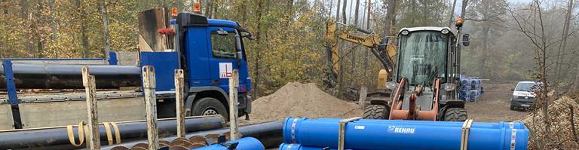
 Photo: Firmengruppe Max Bögl
We are not only assembling the new towers, but also dismantling the old turbines installed in the wind farm. This shows how important good timing is to ensure fast and coordinated workflows.
What are the advantages of hybrid towers?
 Photo: Reinhard Mederer
With their combination of concrete and steel segments, hybrid towers are particularly suitable for inland locations with low winds. This is because the annual electricity yield that wind farms generate can increase by 0.5 to 1% with every meter that a wind turbine gains height. In addition, hybrid wind power towers are designed to withstand the new, more powerful wind turbines and larger rotor diameters.
How does the hybrid tower 2.0 differ from the previous hybrid tower system of Max Bögl Wind AG?
 Photo: Reinhard Mederer
With our hybrid tower system hub heights of up to 190 m can be realized. This makes us the world leader. With the new tower generation - the hybrid tower 2.0 - we need less material while maintaining the same stability. We have also made adjustments to the foundation design, interior fittings, tower segmentation and geometry. For wind power projects, this means that fewer heavy transports are required and therefore less time-consuming approval procedures and lower transport costs. Thanks to the innovative interior design concept, the construction time is further reduced. Overall, our hybrid tower system has become even more economical and, in view of the current market conditions in Germany, is an ideal system for realizing high hub heights.
